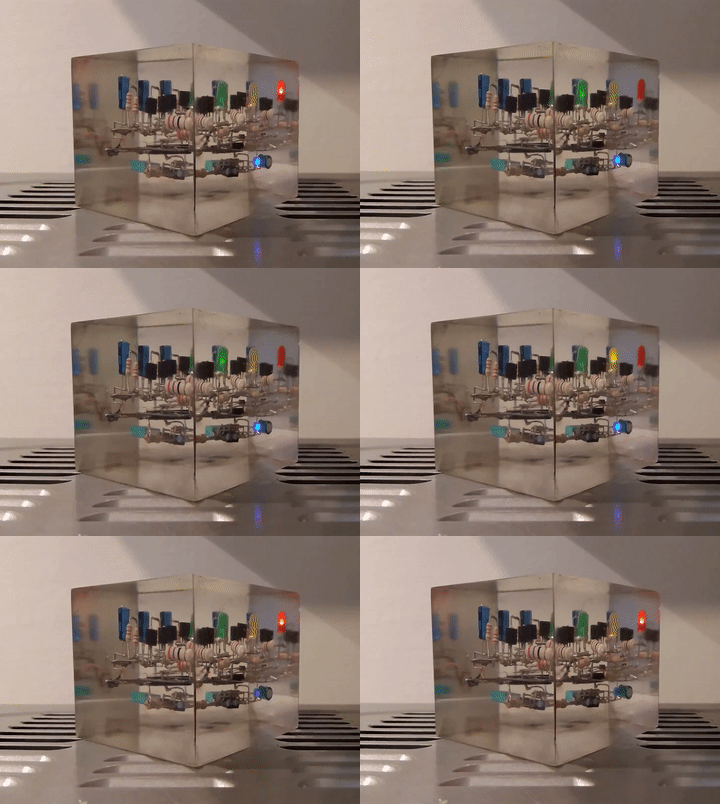
Why and What
Why: I don’t know, random project; the current Covid-19 quarantine is so boring. What: spare parts I wanted to put together. I was playing with a 555 timer I had lying around and I decided to set up a mini-semaphore. To make the whole thing fancier, I also thought I’d go for a skeleton circuit dipped in epoxy resin instead of the same ol’ PCB, just so I could experiment something new.
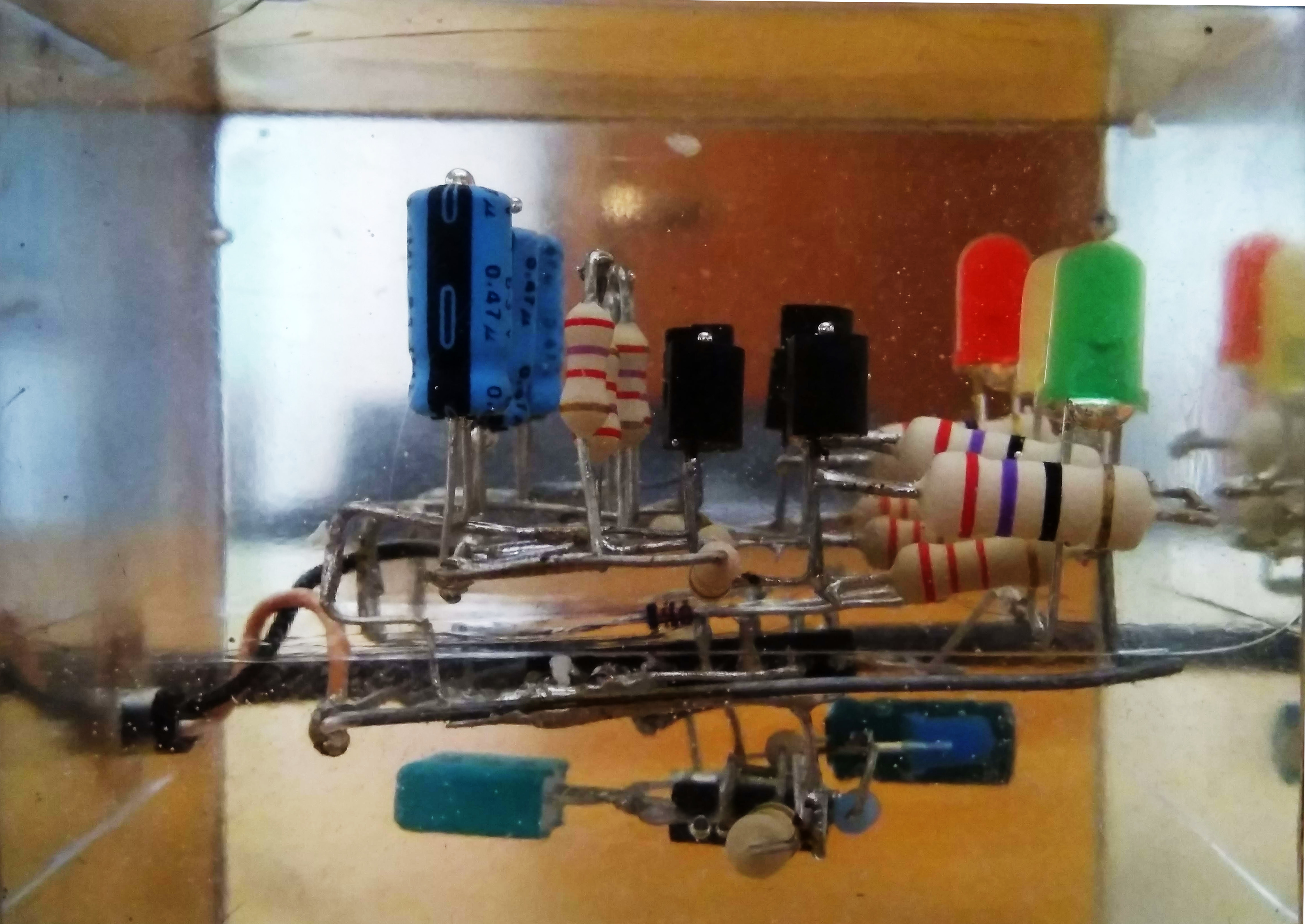
The Circuit
As I always admit, I’m pretty much helpless at electronics, so this took quite a while. Actually, it took a lot especially because I kept drawing 3D sketches instead of an actual circuit I could simulate, but whatever. I wanted the circuit to be powered via USB, so 5v was my Vcc. The lowest level of the “cube” is the “timer stage”, i.e. an LM555 timer IC in astable configuration. The generated square signal is used to light up a small blue LED indicator and then sent to the level above, the “counter stage”.
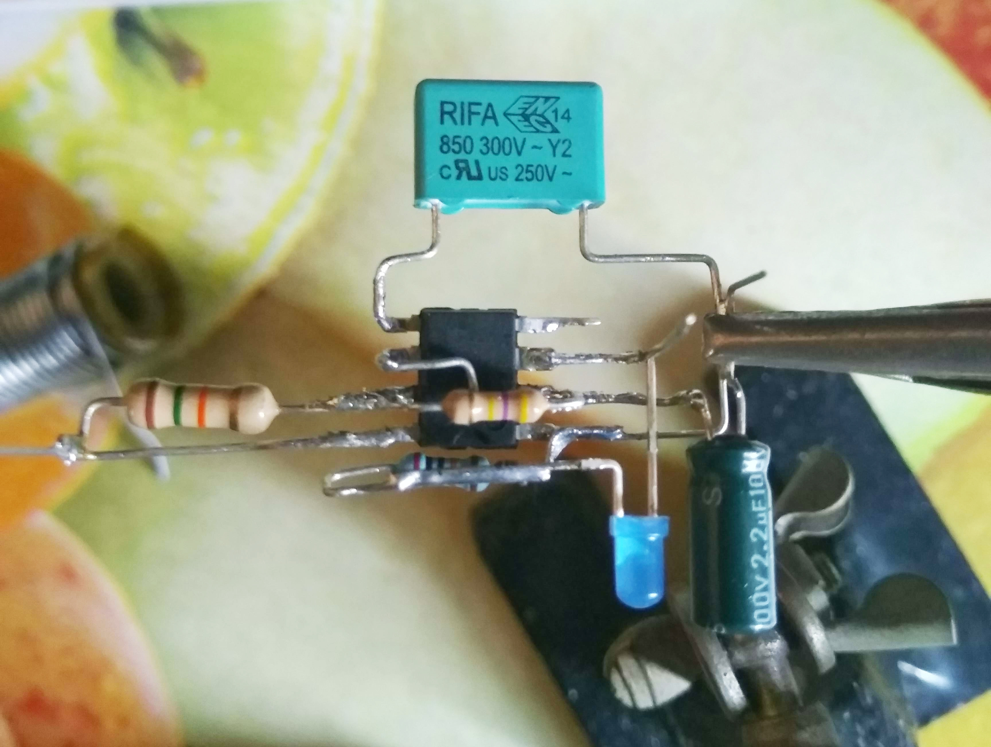
Here, an LM4017 decade counter is used to buffer the impulses by advancing its counter. The first four output lines (so the first four “clock ticks”) are joined together and power the green LED, the next two lines power the yellow one (which has a shorter duration), and the last four lines power the red LED (same duration of green). Obviously, I couldn’t just directly join together these logic lines (a low logic level is GND, so it would short out the high level): instead, I had to somehow create a number of OR logic gates. As I anticipated I chose to only use spare parts I had around, and since I didn’t have any OR gates ICs nor I wanted to solder together a host of transistors, I went for simple diodes.
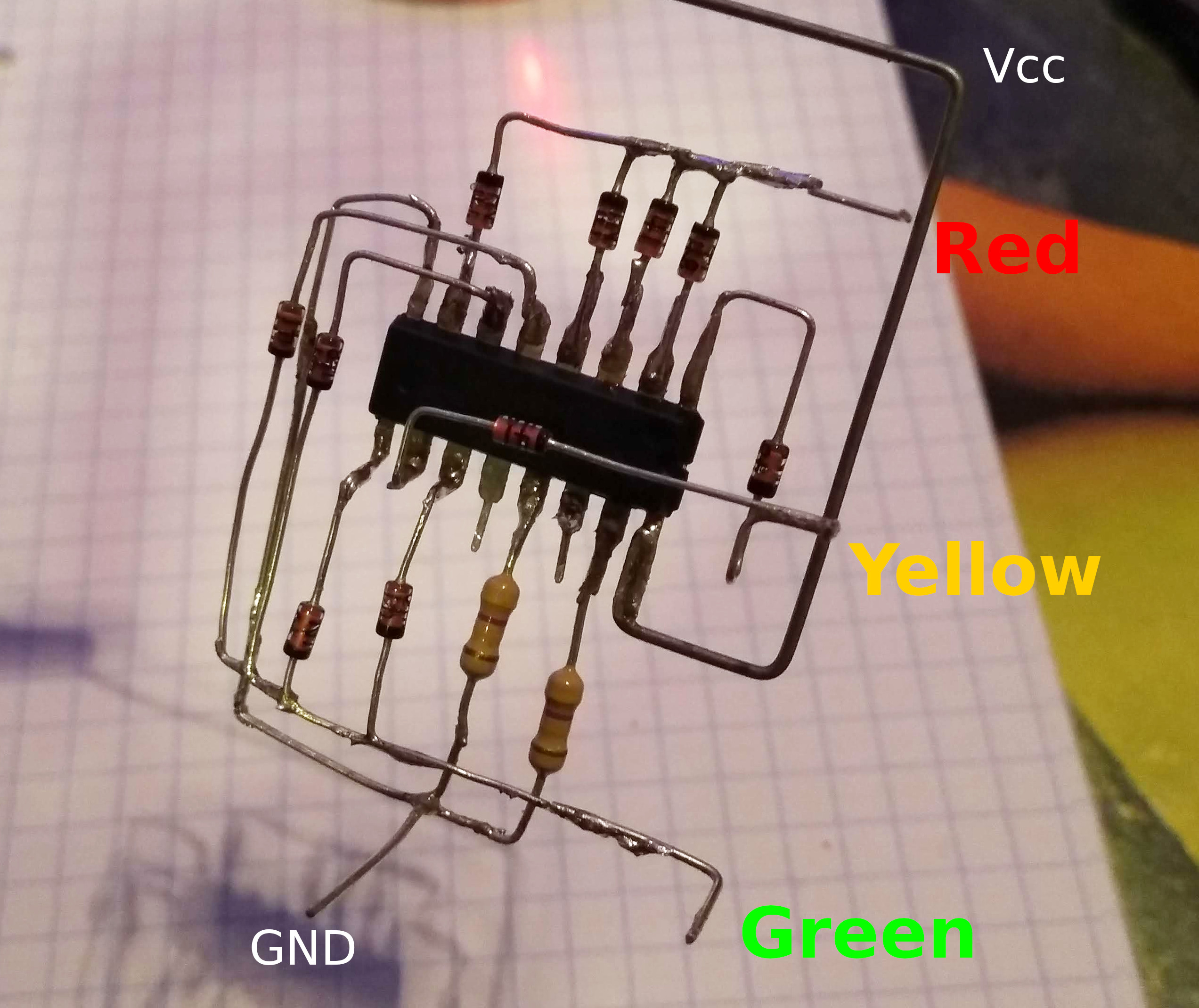
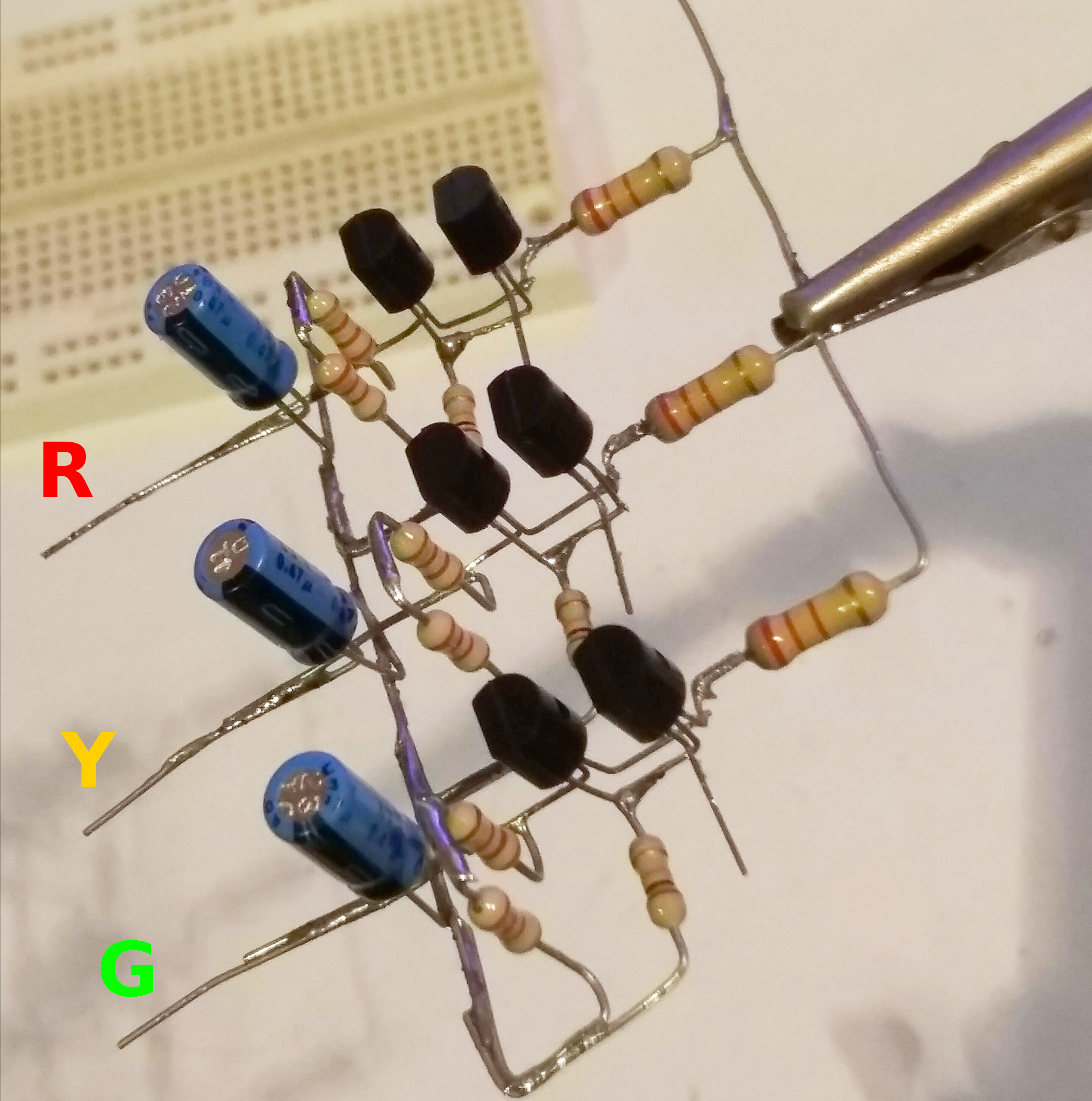
The resulting three lines are directed to the last level above, the output stage, where the logic signals power the three LEDs through two PNP transistors configured as a “double NOT gate”. Again, I chose this configuration with PNPs because I didn’t have enough spare NPNs.
Final Result
After joining the three stages, I built a Plexiglass case to be filled with transparent epoxy resin and cover the whole circuit:
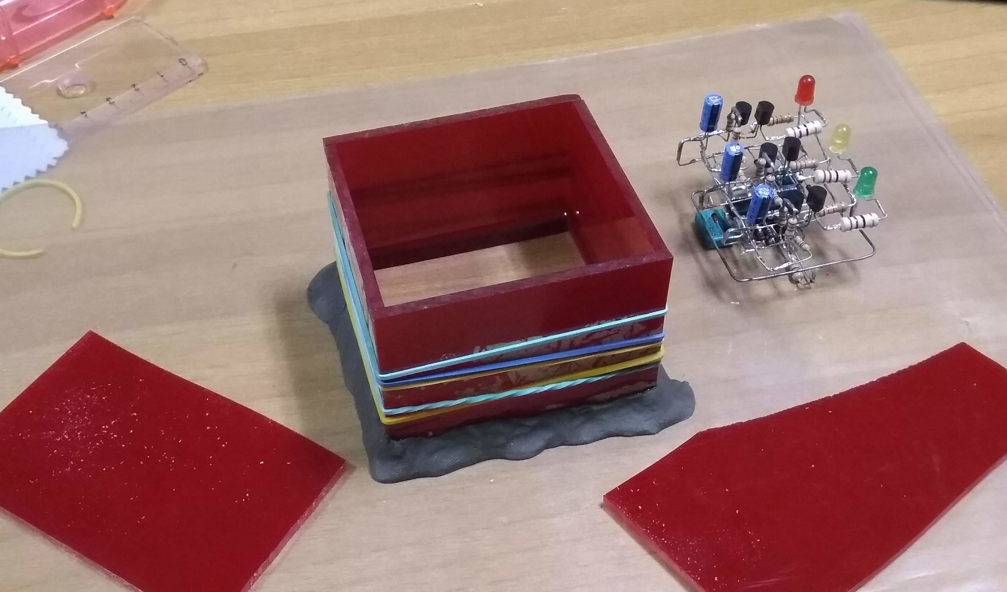
And after one night and a lot of sanding and polishing, here’s the result:
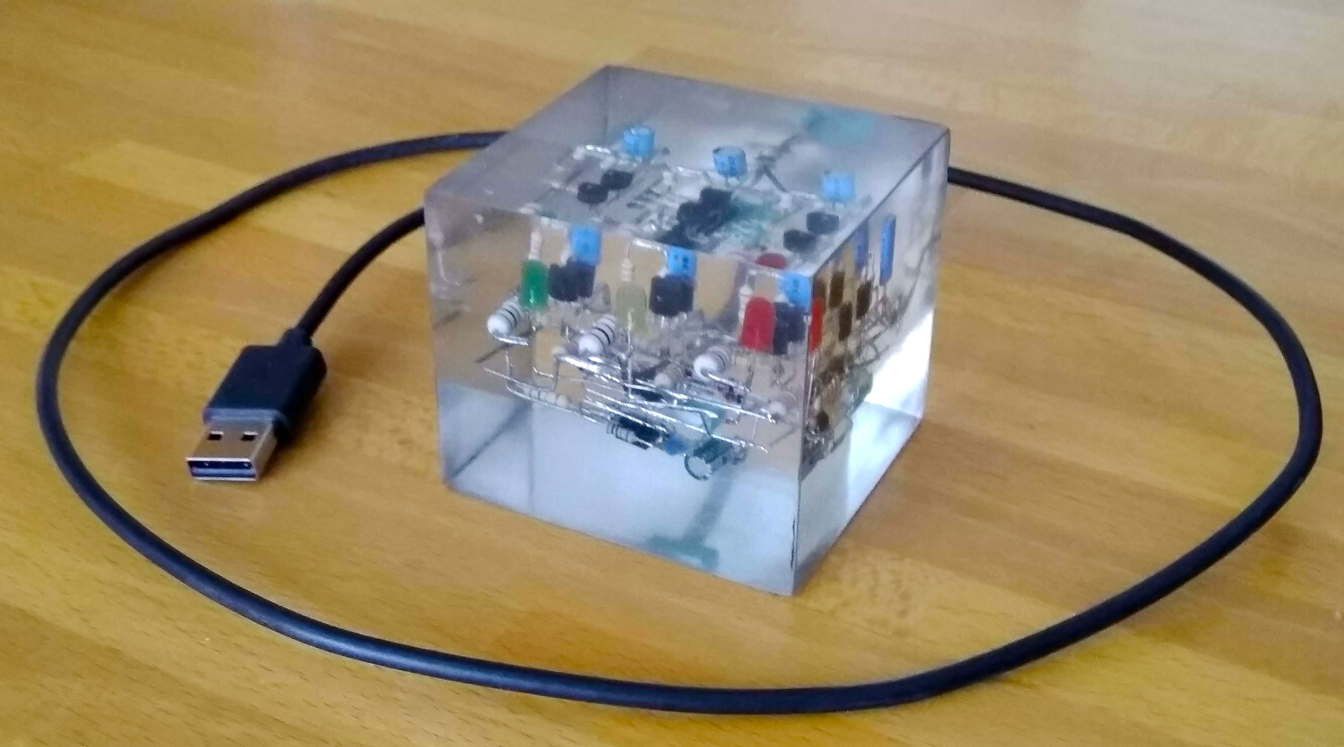
Unfortunately, the green LED turned out to be a bit weak. I knew this would happen because I used the same resistor value for all three colors even though they have different forward voltages, but outside the resin the effect was not this ugly. But whatever, I had fun anyways. Here’s a GIF ![]()
