The Idea
I live in a quite old house, and the heating thermostat is one of those with only a handle to set a threshold temperature, below which it will turn on the heating system. Main disadvantage is at night I either set the temp to 18°C/20°C and pointlessly waste a lot or set it to say, 15°C, and wake up to a frozen house. Another disadvantage: during weekends I’m often out and I always have to get back at late evening with like 10°C.
Time to get a Raspberry Pi and and treat myself.
The Project
What I had in mind was simple: a Raspberry Pi Zero W running a Python loop and a web app to control everything from my phone.
The RPi Zero W is provided with an on-board Wi-Fi chip, so the network part was as easy as a configuration file. It needed a little extra hardware though, to actually control the central heating.
The Circuit
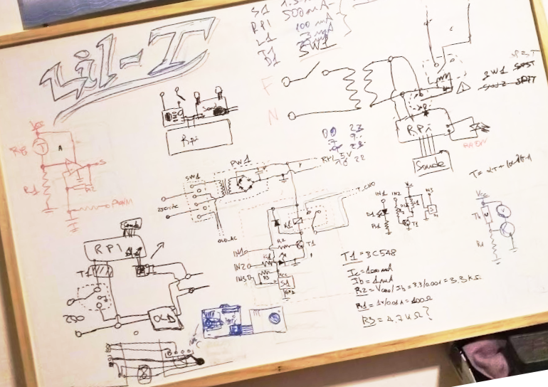
The old thermostat was connected with four wires, and a quick test with a multi-meter proved my suppositions right: two were a 250 V AC line and the other two when bridged together powered on the boiler. Some little sketching and the circuit was ready:
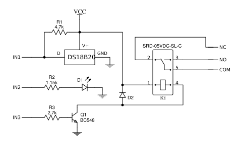
That 5v supply comes from the RPi, as well as the 3 control lines. The first input is a data line to the digital temperature sensor (DS18B29), the second one lights up a status LED and the third switches on the 250V relay. It is driven by a transistor because the coil needs 5v, while the GPIO header of Pis only provide 3.3v. The other extra components are quite trivial: a pull-up resistor for the digital line, two current-limiting resistors and a diode to protect the circuit from the inductive kick of the relay.
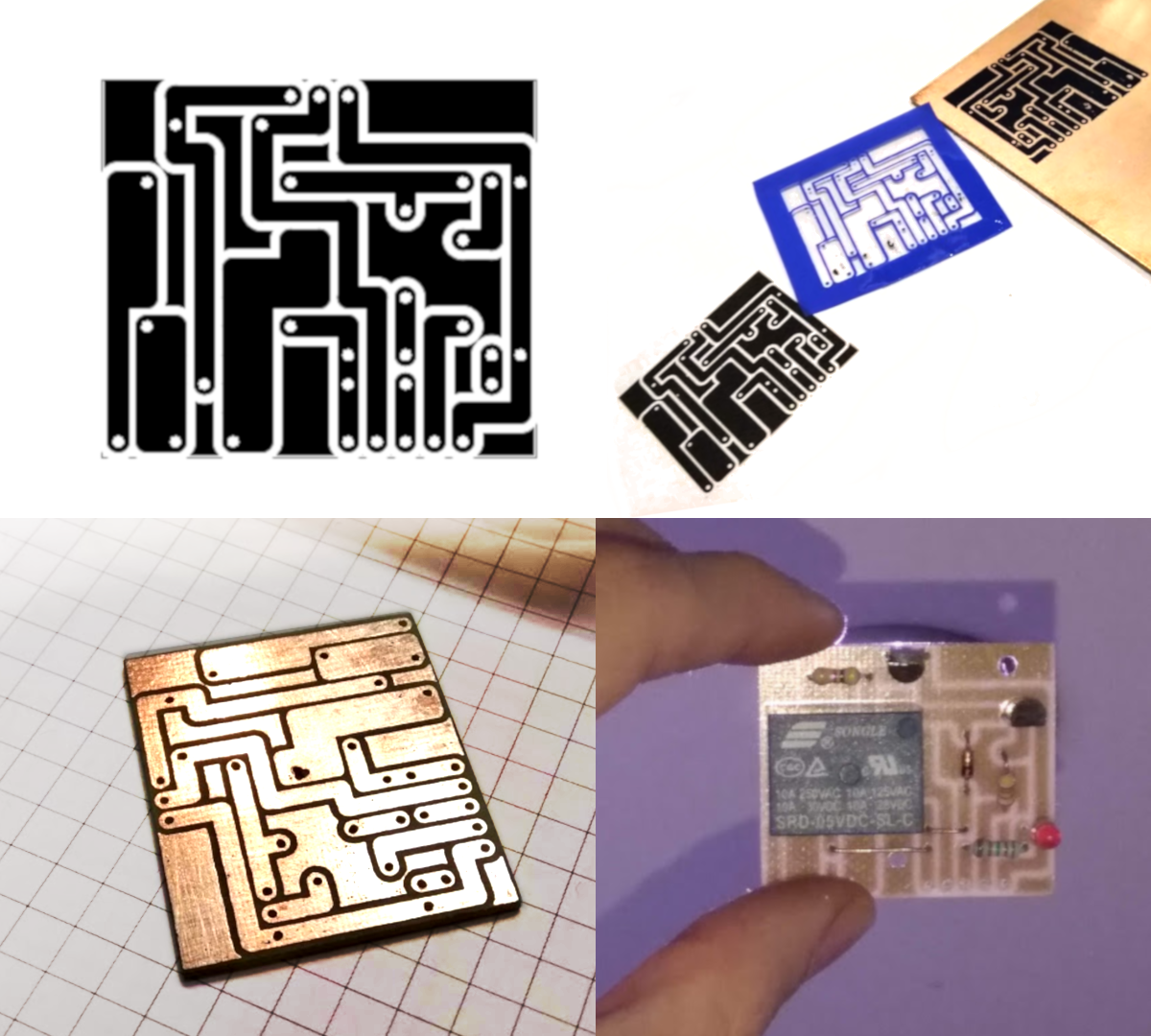
Next up, a PCB to hold it all together:
The Casing
I had quite clearly in mind what it had to look like, so I went for a CAD model and a 3D print. To not waste too much plastic I only printed a skeleton of the box, using a couple pieces of Plexiglas for the more extended surfaces.
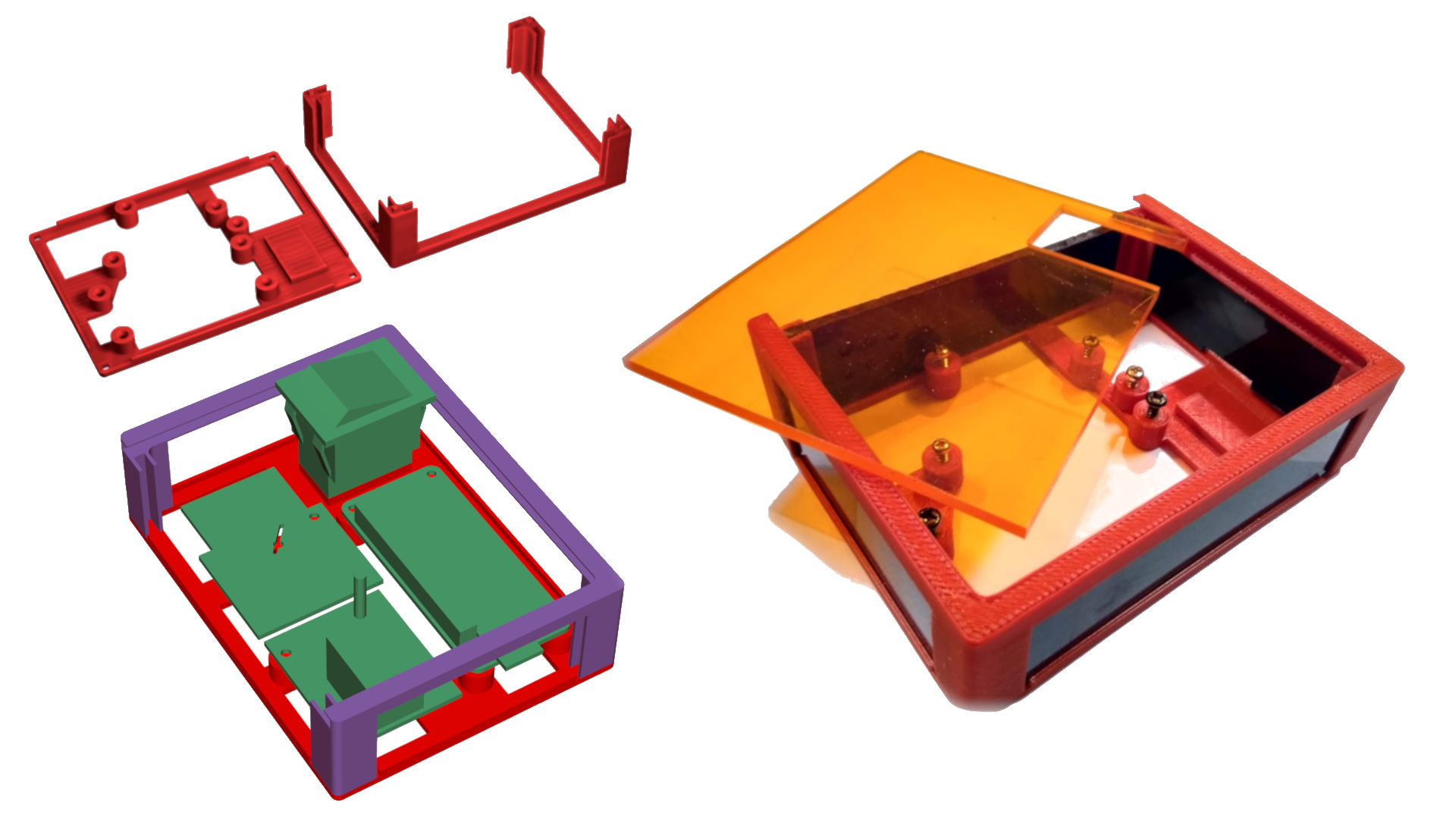
So that’s the whole hardware, plus a switch and a power supply that I kindly borrowed from an old phone charger. Surprisingly enough, it all fit nicely inside:
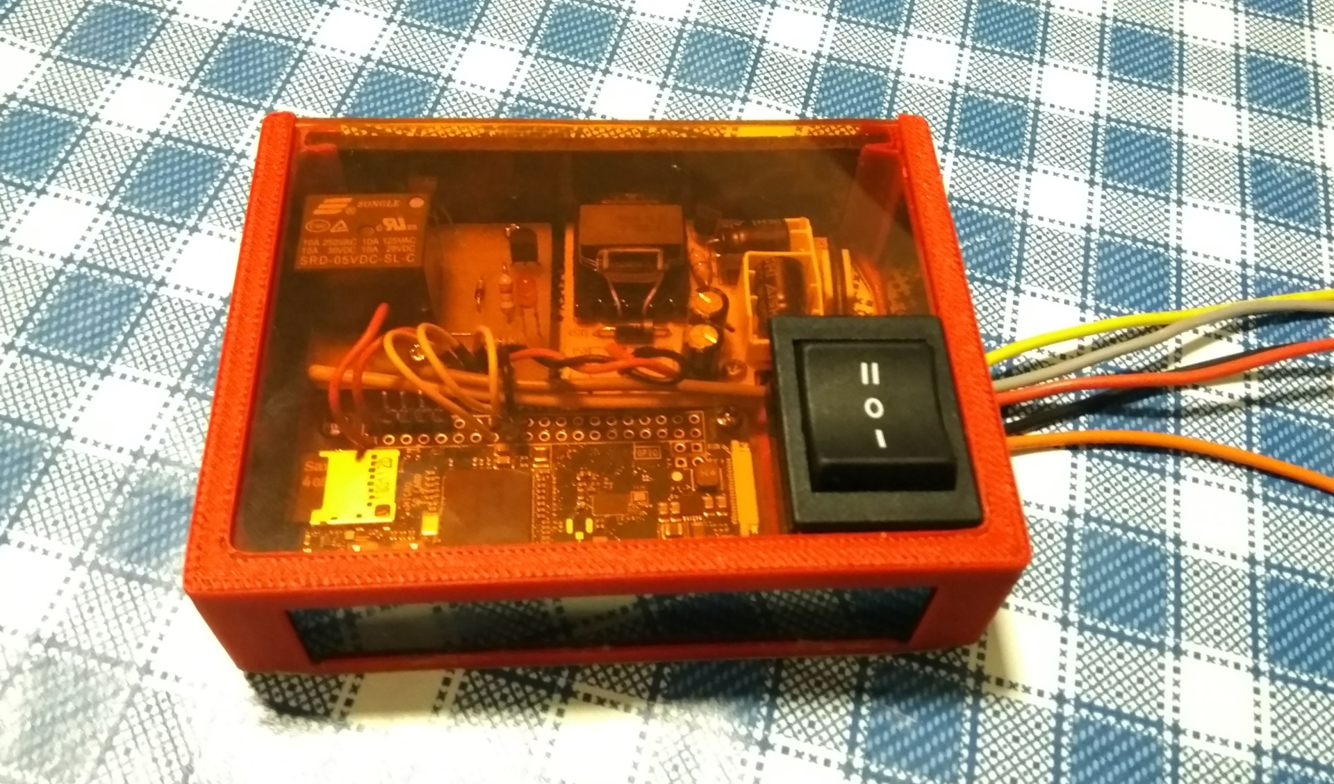
I know, there’s an extra wire coming out and the switch is not the on/off type you expected. Well, I wanted to keep both thermostats, in case mine goes crazy or something inside blows up. So position “II” powers mine and position “I” powers the old one… Better safe than sorry, right?
The Software
First off, the operating system: I wanted something as simple as possible with nothing more than what I needed, so I went for PiCore, a port of TinyCore for Raspberry Pis. The full OS image is 15-30Mb in size, and it operates fully from RAM. What I needed was running a loop and a REST API, so I installed Python with Flask and RPi.GPIO. The project consisted of a couple of files: one was the actual loop controlling temperature and stuff, one was a Flask App listening for requests, and the others where little libraries I made to easily manage hardware communication and the concept of “Time Periods with a target Temperature”.
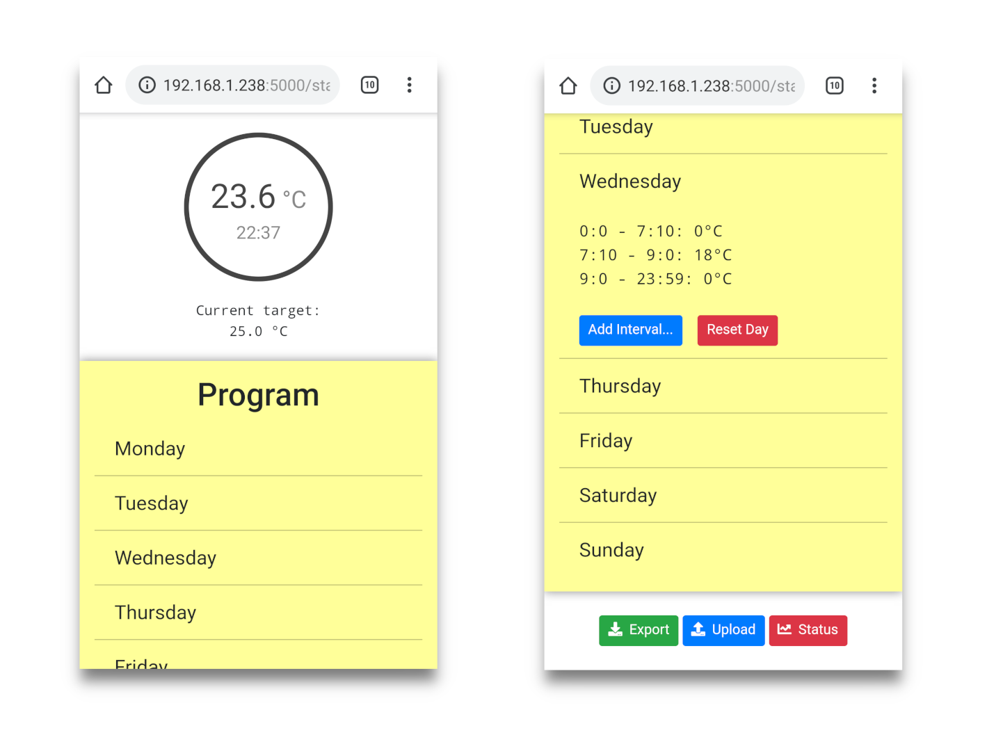
Basically, the user uses the web app to partition the day into time spans, and sets for each of them a desired temperature. For instance, on Mondays I want to wake up at 9.00am with 20°C.
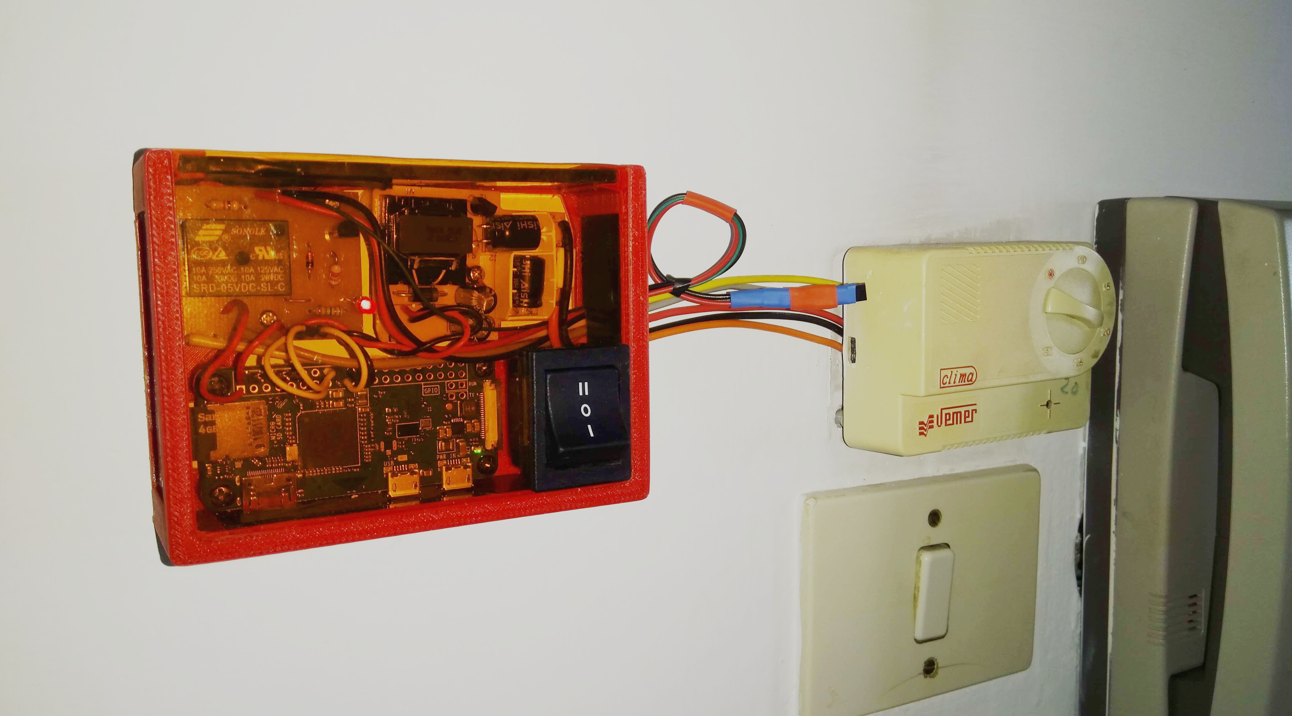
So that’s it. Feel free to contact me for any question or suggestion. And here’s the final result:
Let Me Say a Little Thanks
I feel a little thanks to my father is obligatory. Not everyone has a 3D printer or a tank of ferric chloride acid at home, so thanks for sharing everything with me, all the time.

He’s the kind of person that puts passion for something above everything else, even if it’s others’. So go get a look at his creations here and here, he’s an awesome artisan!